Project based learning started with the goal to help PHCET engineering students develop the skills, tools and character they will need as future leaders in the world of engineering practice. Project-based learning (PBL) lies at the heart of the engineering program, as the key mechanism for students to develop and reflect on their individual engineering leadership skills. Project-based learning (PBL) is considered an alternative to the teacher led classroom model. In fact, this will integrate theory and practice. The benefits are plenty including improved designing of circuits skill, understanding concepts, people and processes in an organisation. The core idea of PBL is that real-world problems capture students’ interest and provoke serious thinking, as the students acquire and apply new knowledge in a problem-solving context.
Department
Mechanical Engineering
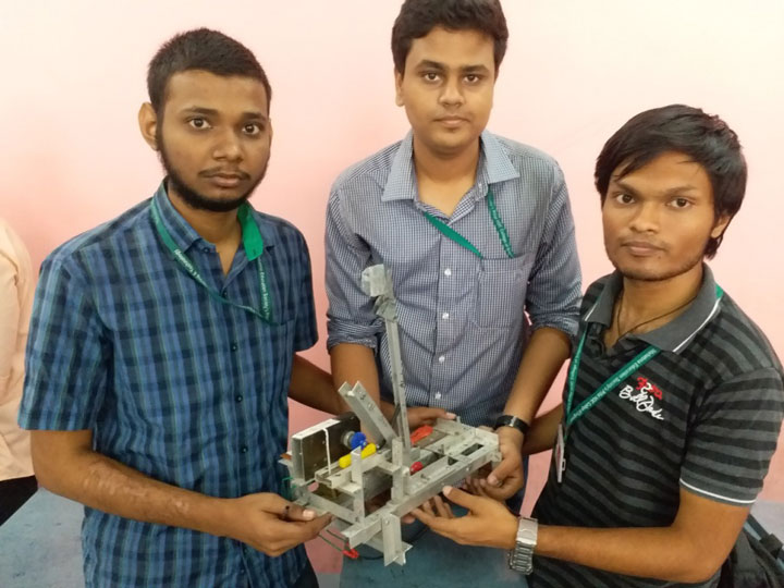
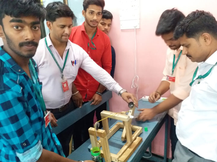
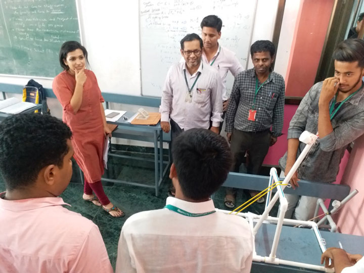
Pillai HOC College of Engineering & Technology, Department of Mechanical and Automobile Engineering organised PBL on 11th April, 2018 for third year students and 12th April, 2018 for second year students. Totally 66 teams for third year and 64 teams for second year have demonstrated their projects. The necessary equipment and components provided by the college freely to the students to complete their projects. Evaluation was done by panel of faculties by standard rubrics.
The problem statement for PBL are as follows
Second Year
Topic: CATAPULT
Design and Construct a Catapult, so that when the swing arm is pulled back to the desired angle and triggered / released, it propels a ball / mass forward. The triggering of the arm has to be done using electronic means. The ball / mass has to be considered from at least any two different classes of materials. The ball / mass is expected to land on a box or a bucket positioned at some arbitrary distance from it, in the very first bounce. The best design of catapult is the one that throws the ball in the box / bucket at various arbitrary positions, a maximum number of times out of the given 5 attempts.
Rules for design / construction of mechanical catapult:
- The mechanism must use at least a 4-bar (or 5-bar, 6-bar, etc.) in order to accomplish the task.
- The length of swing arm supporting the container (carrying the ball / mass) should be such that the container should be positioned at a maximum possible distance of 300 mm from the pivot.
- The swing arm should be preferably scale-marked or calibrated for enabling the measurement of position of the container.
- The container position should be adjustable on the swing arm and can be fixed when in operation. The range of movement of the container on the arm should be a minimum of 200 mm to a maximum of 300 mm from the pivot.
- Diameter of the container carrying the ball / mass should be at least 40 mm, or should be able to contain a Ping-Pong (table-tennis) ball in it.
- Students are free to use any combination of materials for construction. Wood may be used as the main construction material for the linkage. Typical materials for generating potential energy (elastic materials) include—rubber band, linear / torsional steel / plastic springs, elastic beams, twisted ropes etc.
- The ball / mass should be hand-loaded in the container during the competition. Each team may then use hand (muscle-power) or a standard motor (3-4.5 VDC worm-gear set) to power the swing arm so as to create potential energy in the system.
- However, after loading (if motor is used-check with robotics laboratory regarding availability), teams will be permitted only to turn on the switch connecting power to the motor, for triggering. This means that each valid design must have an automated release mechanism which will disengage the motor during the throw. The ball must be released within 30 seconds of turning on the motor.
- Each team must take the responsibility of the safety issues concerned with the construction and operation of the catapult, so that it does not harm others. If it is found that the catapult is not safe for operation, it may lead to a penalty or disqualification.
The various links may be connected together using any means (glue, nail, bolts, etc.).
Rules for the use of triggering mechanism:
- Students are free to use any basic electronic device/s (as stated in ‘Industrial Electronics’ syllabus) so as to trigger the swing arm of the catapult to propel the ball / mass.
- The triggering may be done by a simple switch mechanism, or operable through your smart phone or a PC system for which appropriate programming needs to be done.
Students are advised to conduct various test runs using different combinations of the adjustable parameters of your design / mechanism and document / tabulate the same in your report. These shall be used to create graphs between different adjustable parameters. At least 2-3 graphs on the same are expected. This information shall be used during the final performance test for setting the right combination of different parameters of your catapult design, so that the ball / mass is propelled to the right spot for each setting.
Also, the report should include the following –
- Introduction – should include Goals of Project, General Background on Catapult, Forces involved, Energy Transformations, Construction methods and Materials used.
- Design (estimation of dimensions of various parts) – Optional
- Computerized (CAD) figures showing assembly and details of the catapult.
- Catapult physics (analytical estimate) to find the distance (x) by which the ball / mass is thrown measured from the catapult arm or the front edge of the base plate. Figure is given as follows, for reference.
- A computer program (structured / object-oriented) using any software (for e.g. excel) so as to simulate / test-run to estimate the distance (x) as per the design calculations of step (iv) above.
- Results – (a) Simulation (with printout, described in paragraphs), (b) Catapult Testing (tabulated and described in paragraphs), (c) Description of changes made (if any) to improve performance
- Conclusions – Did the catapult perform as expected? Where was the mechanical energy lost? Did catapult illustrate the conservation of energy and projectile motion? How could you improve your design or construction to make it work better?
- Tabulated cost analysis for constructing the catapult.
- References (all sources of information should be clearly cited).
- Contribution details of each participant of the group.
- Note: Students may include additional information and data, as per listed in the Catapult and Trebuchet Handbook 2013-14, from Dr. Hair’s website.
Related Subjects: Mechanics (projectile motion and dynamics), Kinematics (Theory of Machines-I), Mathematics, Computer Programming Concepts, Material Technology, Industrial Electronics, Production Process and Machine Shop Practice.
Third Year
Topic: Aeolipile / The Hero Engine
A hero engine or the Aeolipile is an ancient device that uses steam to produce rotational motion. Water is heated inside a chamber and the steam produced is released from a pair of nozzles. This produces a torque causing the device to rotate.
In the 1st century AD, Heron of Alexandria described the device and many sources give him the credit for its invention. The aeolipile Heron described is considered to be the first recorded steam engine or reaction steam turbine. The name – derived from the Greek word Aeolic and Latin word pila – translates to “the ball of Aeolus”, Aeolus being the Greek god of the air and wind.
Students will be asked to design in solid works, generate a mathematical model and finally build and test the device. The device should be able to rotate at a certain peak RPM, for a fixed amount of time and it needs to be attached to a generator to generate a voltage of at least 1V. The device will be developed in multiple stages. Students will be tasked to do the following
- Model the device and derive equations for the following (20 marks)
- Time required for the device to start spinning
- Time required for the device to stop spinning
- The angular velocity for the device assuming no friction and that the fluid is in – compressible
- The pressure that is developed inside the boiling chamber
- The torque generated when the chamber is prevented from rotating
- The relationship between the angular velocity and the voltage generated
- Detailed assembly drawing of the device that includes the boiling chamber along with the nozzles, the attachment of the chamber to a generator or a motor with leads that can be used to measure the voltage. The device should be fixture correctly such that chamber does not wobble. Students are encouraged to watch videos online (on YouTube) of the different types of designs other people have developed. They should analyse pros and cons of the different orientations (horizontal and vertical) before picking their own design. Also note that the leads should not be rotating.
- Fabrication of the device. The chamber must be made using materials that have a melting temperature of at least 200 ➦C or above. Students should also try and use low friction bearings for the attachment of the chamber to the fixtures. There should also be a way to refill the device with water when needed and the reseal for further testing.
- Testing of the device to measure the time to start and finish, the final angular velocity and the voltage generated. The device should be supplied with no more than 100 ml of water. It should start spinning within 1 min of supplying heat and stop within 10 minutes. Students should assume that we will be supplying heat with a candle or a burner that can generate heat of around 50 watts. Students should also ensure that the device is safe to operate.
Related Subjects: Mechanics (projectile motion and dynamics), Kinematics (Theory of Machines-I), Mathematics, Computer Programming Concepts, Material Technology, Industrial Electronics, Production Process and Machine Shop Practice, Thermodynamics, Heat Transfer


